
Visit 4CELNK.com for information about 4CELNK-YR No-Tools No-Waste Cable Clips.
Select the tax and shipping options using the drop-down menus. Don’t pay WA sales tax if you’re not in the state (see note below price list). Please note that current orders ship in approximately 3-4 days.
| 4CELNK FRONT Bracket (1) Front / side bracket Plus complete hardware (#2016-010-100) | $59.00 + tax + shipping |
| 4CELNK REAR Bracket (1) Rear / under-seat bracket Plus complete hardware (#2016-010-101) | $59.00 + tax + shipping |
| 4CELNK FRONT Bracket Pair (2) Front / side brackets Plus complete hardware (#2016-010-102) | $109.00 + tax + shipping |
| 4CELNK REAR Bracket Pair (2) Rear / under-seat brackets Plus complete hardware (#2016-010-103) | $109.00 + tax + shipping |
| Most Popular 4CELNK 4-Bracket Set (2) Front / side brackets (2) Rear / under-seat brackets Plus complete hardware (#2016-010-104) | $209.00 + tax + shipping |
| Best Value 4CELNK 5-Bracket Set (2) Front / side brackets (3) Rear / under-seat brackets Plus complete hardware (# 2016-010-105) | $259.00 + tax + shipping |
A note about state sales tax I reside in WA state. If you live in WA state, I’m expected to collect WA state sales tax. If you live outside WA state, the state cannot compel me to charge you, even though they believe they’re entitled to that money. Similarly, they cannot compel you to pay me, since you don’t even live in WA. However, any sales tax that I do receive has to be paid to the state. So, please, PLEASE be sure to correctly choose the drop-down choice for both sales tax and shipping. I’m required to provide the option for WA residents, and if I put that one last, I’ll constantly be having to pay it myself because nobody will see the other option. So, pay attention. If you’re not from WA, click the drop down and say so. ‘Cause if Paypal says you chose the option to pay WA state sales tax, I have no choice but to retain and forward that sales tax. Sorry.
Getting to know 4CELNK™
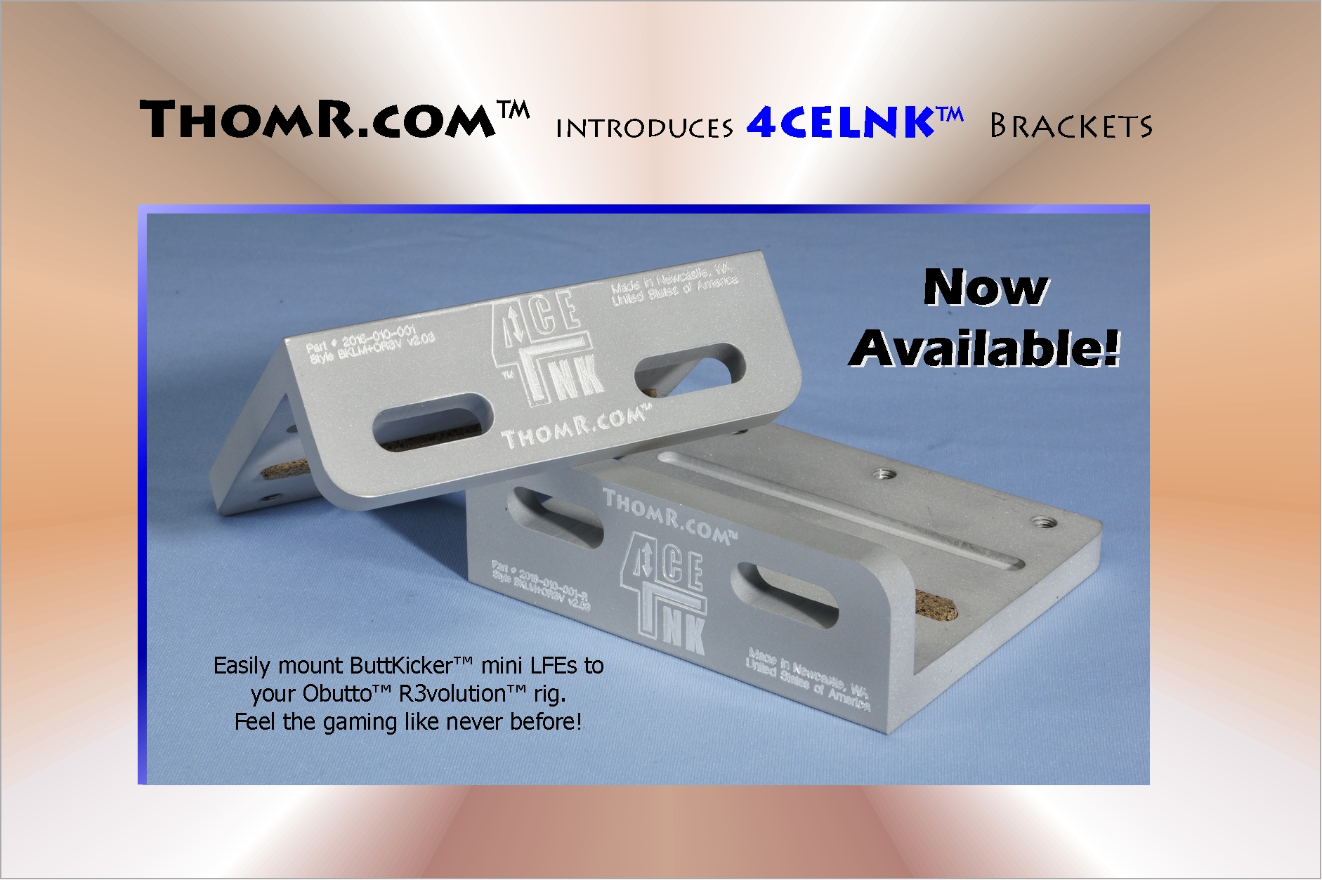
4CELNK Brackets optimally attach Guitammer™ ButtKicker™ mini LFE tranducers to the rectangular and square tubing used in Obutto™ R3volution™ gaming cockpits, for high-performance haptic and kinetic feedback.
")
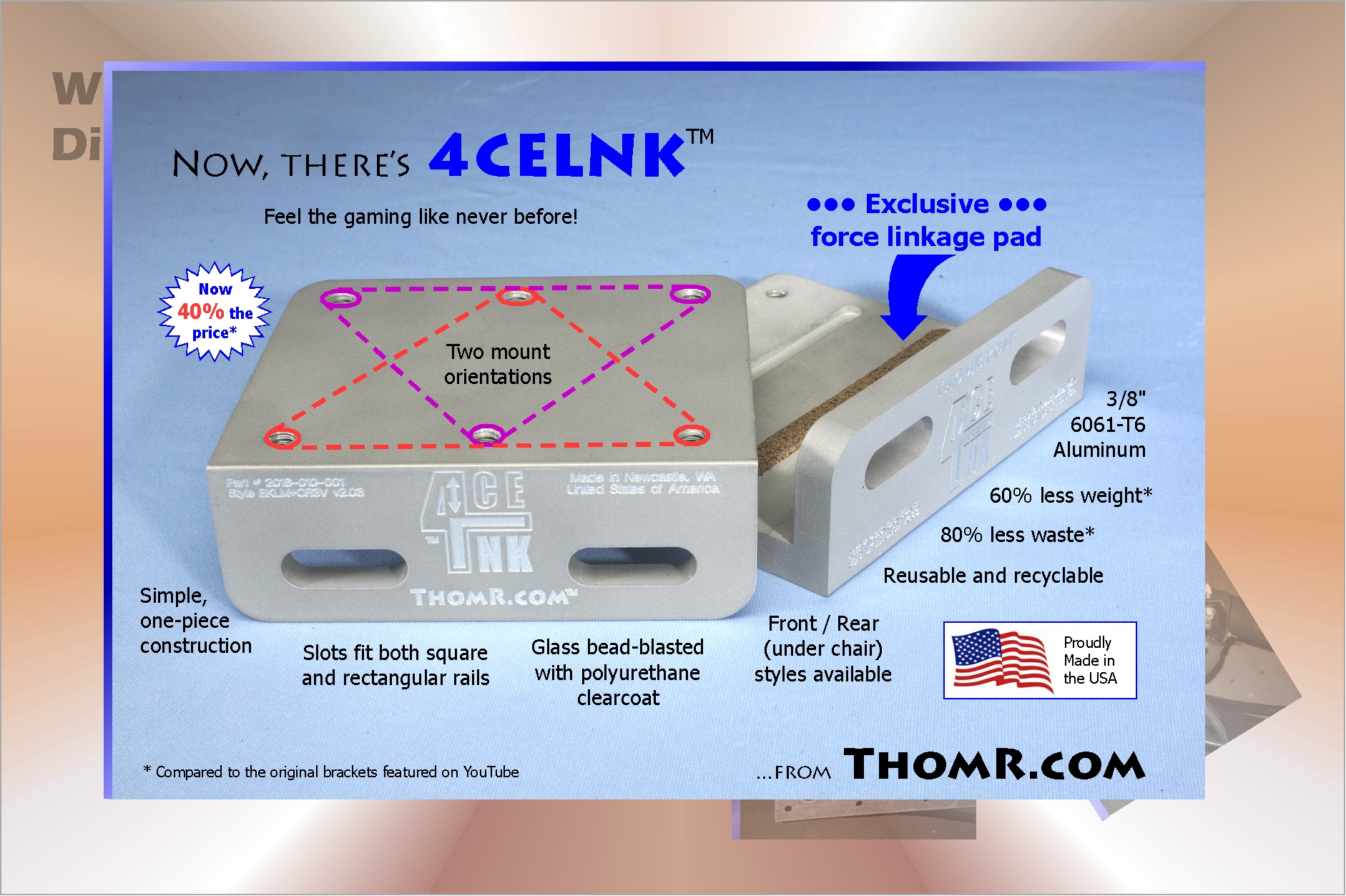
No longer are random hardware-store parts needed to get your gaming vibe on. Now there’s the redesigned 4CELNK Brackets (pronounced “force link”), letting you feel the gaming like never before. This new design is simpler and easier to install, and they weigh about half what the original ones did, for clearer, stronger kinetic feedback. You might find you can even run at lower amp settings for the same sensation, improving performance and reliability. But best of all, get this: they’re 40% the cost. That’s not a misprint: they are indeed 60% lower cost than the original brackets we made for the YouTube video.
To learn more details about 4CELNK brackets, click or tap to expand the items below.
4CELNK Brackets optimally attach Guitammer ButtKicker™ mini LFE transducers to the Obutto™ R3volution™ gaming sim-rig. These brackets just plain work right: no muss, no fuss, no bother. The 4CELNK design supports several mounting positions, and the precision machining ensures everything lines up perfectly.
It’s the secret sauce. The reasoning is a little involved, so it’s down at the bottom of this section. Essentially, if it wasn’t there, the far side of the bracket (away from the bolt heads) can flop up and down during big shakes, making a rattling sound even though the bolts are tight. It’s not a flaw, it’s just how it works when you’re dealing with a thin-walled tube in compression. The cork pad creates a two-point solid contact for the LFE transducer to kick butt through. (That’s the technical term)
Installing 4CELNK™
4CELNK Brackets optimally attach Guitammer™ ButtKicker™ mini LFE tranducers to the rectangular and square tubing used in Obutto™ R3volution™ gaming cockpits, for high-performance haptic and kinetic feedback.
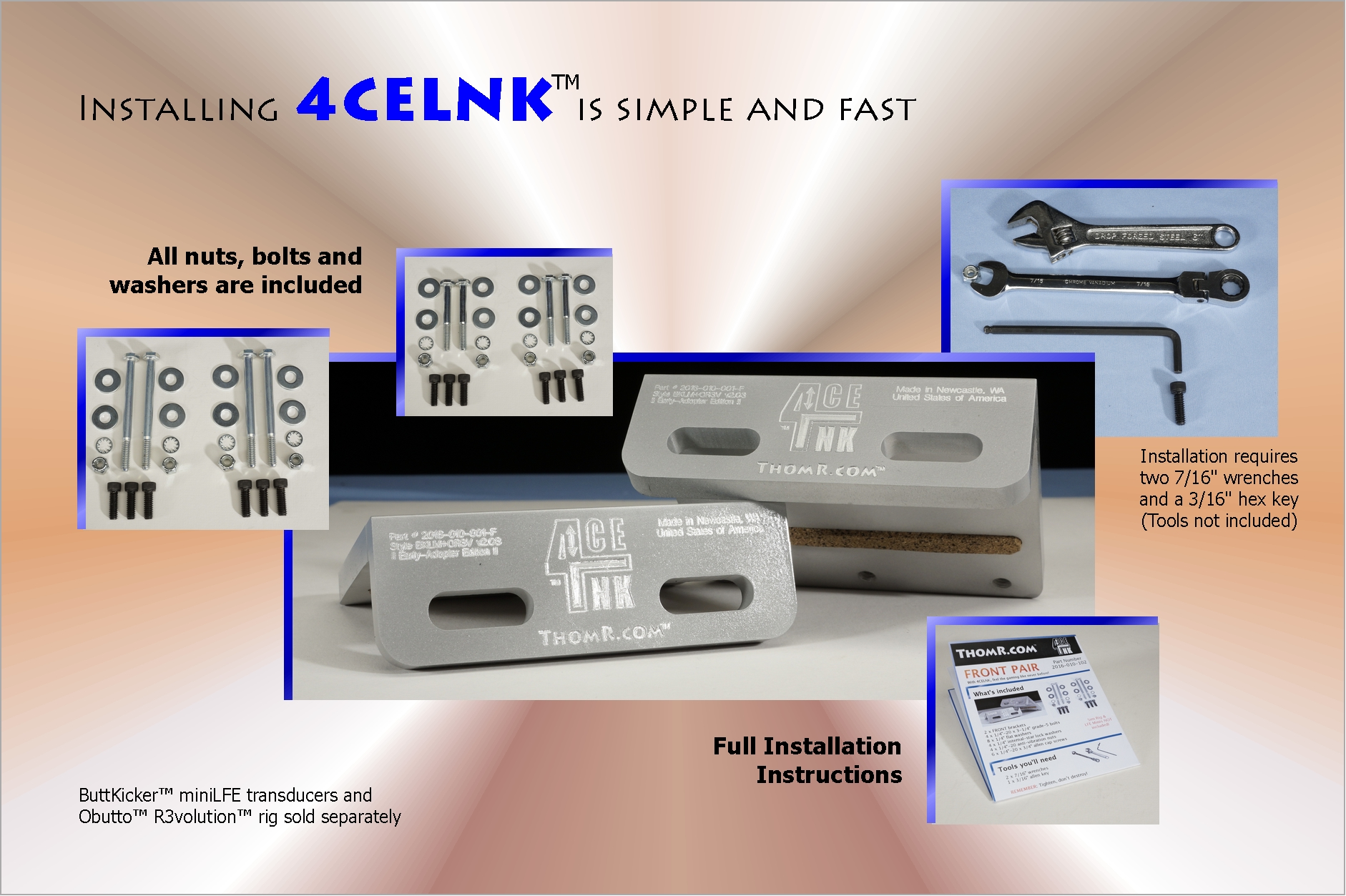
The updated design provides a much simpler, faster install, with less chance the bolts will loosen. The new design also gives greater overall performance because of the reduced mass of each bracket. Click the images below to view the sheets as printable GIF images. If you want to store them, or if you need to use a screen-reader on them, you can download the PDF instruction sheets for the Front Pair and Rear Pair (~25MB each).
")
")
proper support = better performance
Getting the most of your rig, the mini LFEs and your new 4CELNK brackets means paying attention to where those vibrations are going.
Think of it this way: vibrations can’t go through soft, jiggly things, but go right through hard things. You want the energy to stay in the rig, and none going through to the floor. The rig is hard, the floor is hard. You want the “soft” parts closest to where the energy is being generated. Okay, that’s confusing, I admit. Essentially, if you have multiple layers, with the shaking moving from top to bottom, you want soft-hard-soft-hard layering so that the energy gets trapped inside the soft layers, and is instead reflected back by the hard layers. Yeah, it actually does work that way.
") What that means is that the best performing setup is to put a single rubber mount between the shaking and the non-shaking parts. Guitammer and Obutto both strongly recommend that when you use ButtKickers, you should support the rig on vibration-isolation / -dampening pads. Ideally, those are then sitting on, or mounted to a concrete slab. You can find isolation pads in a variety of places, but you’re looking for something that looks about like this.
What that means is that the best performing setup is to put a single rubber mount between the shaking and the non-shaking parts. Guitammer and Obutto both strongly recommend that when you use ButtKickers, you should support the rig on vibration-isolation / -dampening pads. Ideally, those are then sitting on, or mounted to a concrete slab. You can find isolation pads in a variety of places, but you’re looking for something that looks about like this.
If your only option is to put the rig on a padded and carpeted floor, even if it’s on a concrete slab, you want something hard so all the energy isn’t just passed into the carpeting. Thus, the path downward is through the rig (hard), then the vibration-isolation mounts (soft), then the layer of plywood (hard), carpet and padding (soft), and the underlying floor (hard). Oriented-strand board, OSB works well too, but tends to give more splinters! Some indoor/outdoor carpeting is also firm enough that you could get away with using it…but only under vibration isolation mounts.
The one thing you want to avoid is directly placing the vibrating rig on the carpet, because the majority of the shaking power will go into the floor and you’ll never feel it. You’ll always be trying to turn up the amp, and eventually either the amp or transducers will fail from being over-driven. Similarly, don’t put the vibrating rig directly on a hard surface either…it will probably start moving across the floor!
Getting the most from your lfes
The Obutto R3volution rig’s LCD monitor stand has square-sectioned support rails that run next to the rectangular front rails where the 4CELNK brackets and mini LFE transducers attach. The following diagram shows some of the ways to mount them.
![]() According to measurements I found on the Obutto Web site, there is 6 cm (2.36 inches) from the outer face of the side rail, to the outer face of the square monitor stand rail. Since the square rails are 1.2 inches on a side, that leaves about 1.15″. The 4CELNK brackets are 0.375″ thick, and the bolt head adds about another 0.25″, with another 0.070″ for the washer. That leaves just over 0.45″.
According to measurements I found on the Obutto Web site, there is 6 cm (2.36 inches) from the outer face of the side rail, to the outer face of the square monitor stand rail. Since the square rails are 1.2 inches on a side, that leaves about 1.15″. The 4CELNK brackets are 0.375″ thick, and the bolt head adds about another 0.25″, with another 0.070″ for the washer. That leaves just over 0.45″.
Normally if it was on carpet, I’d say that might be a little tight….except the rig is supposed to be up on vibration isolation mounts. It’s not likely you’ll mount the monitor stand on vibration isolators also, because the stand height is adjustable. The isolators, then, put the rig up by 1.75″ (uncompressed). That’s more than enough clearance. The following diagram shows three of the typical mounting configurations for the front rails.
Those nice tall isolation mounts might not suit your needs, and so you might go with one of the smaller cylindrical isolation mounts. This will help, but again it’s going to be better on a concrete slab than on a wooden floor or with carpeting.
Sneaky tip: If you have no other option than to use your rig on a carpeted floor, you can get much better vibration isolation performance if you put down a big sheet of 3/4″ plywood as a base on top of the carpet. On top of the plywood, use isolation mounts, with the rig mounted on top of those. Having a (relatively) hard isolation layer directly on the soft carpet will vastly improve the performance of the isolators. Without the plywood, the isolators will barely flex at all, sending all that energy into the carpet and floor. Paint or otherwise cover the plywood for appearance, but make sure the isolation mounts are in direct contact with both the plywood and the rig’s frame.
If for some reason you really needed to use the right-hand style, the chance of contact can be removed entirely just by raising the rig 1/2″ or so. Otherwise, the recommended way is on the left, and if you have to stay on-the-carpet, the middle one work well too.
lfe mount direction
There are two ways the mini LFE transducers can be mounted onto the 4CELNK bracket, but unless there’s some physical interference, mount the LFE transducers so the vertical metal bracket plate (on the LFE) is on the same side as the 4CELNK slots.
Why? You won’t see very much difference, but since the LFE is pressing down/up against three points, it’s better to have the two points close to the attachment point, rather than farther way. It improves the force transference into the frame, improving the LFE efficiency. The brackets are rigid enough, however, that you might never notice any difference.
The photo below shows the two available mounting directions. Whenever you can, use the mounting style on the left in the picture, and avoid the one on the right.
")
Push those Unders up
One thing that might prove confusing, or that you might not even notice, is that you have to **press** the rear / under-seat brackets up against the square frame rail. This picture shows the problem (granted it is also using a front / side bracket, but the effect is the same). Notice that gap above the horizontal part of the bracket? Yeah, can’t be havin’ that!
")
It’s important the 4CELNK cork force linkage pad be in firm contact with the frame rail. Be sure to push up on the bracket when you mount it. You want the inside corner of the bracket on one edge of the tubing, and the pad **pressed against** the opposite edge. When the bracket is not properly seated, the LFE vibrates in-air, with very little of the force transmitted into the frame via torque, instead of linear kinetic motion.
This isn’t nearly as much a problem with the front / side brackets, because gravity generally ensures it will be pressed into place when the bolts are tightened. If not, then push down on those while you’re attaching them.
The updated backstory
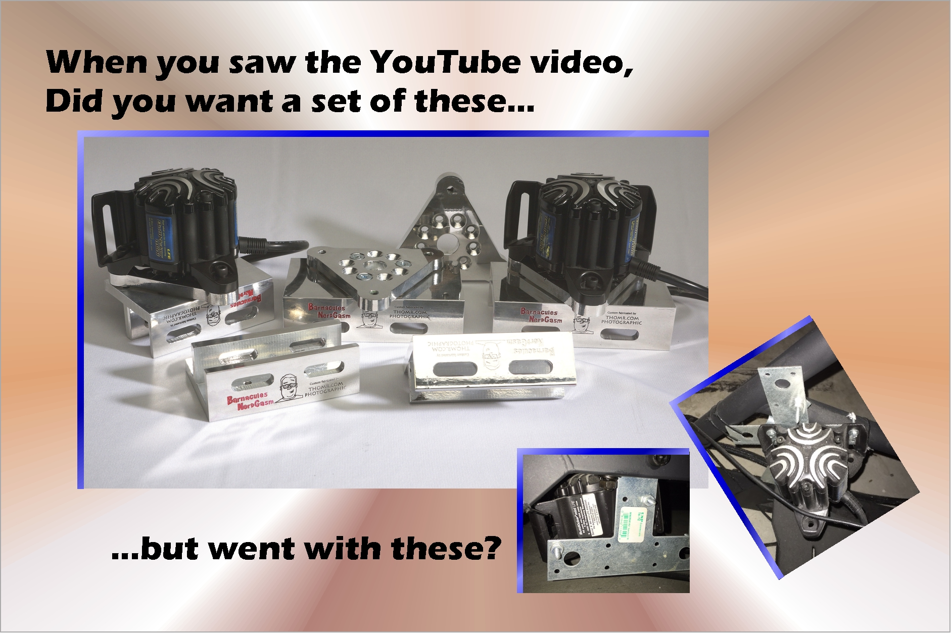
Many know about the Barnacules collaboration we did about a year ago, making a set of amazing, polished and engraved, monster heavy-duty, CNC-machined brackets. You might have even come here after seeing that video and wanting a set.
")
It turns out that set was insanely expensive to make, and would always have been uneconomical to make, not matter the machine capabilities. When you remove 70+% of stock material and recycle it, you’re essentially throwing away a huge amount of money with every unit. And so, the price required to make a full 5-bracket set, turned out to be over $600, and we all knew that was way too much.
This past fall, after I kept getting asked by people with more sense than money, I decided that maybe the right thing to do would be redesign them. After all, I’m an engineer, right? Price is just one more variable in the equation that constrains how you make something, right? So, working with “Austin” (thanks, man!) I came up with a universal design that fit both tubing shapes, one that would be as as strong and efficient as the original design, and MUCH less expensive.
")
") As with so many things, there were errors made along the way, like this $50 bit on the very last pass of cleaning out the angle radius, that came upon more metal than it expected, and turned a tiny horizontal cut into a terrible, bad, no-good thing.
As with so many things, there were errors made along the way, like this $50 bit on the very last pass of cleaning out the angle radius, that came upon more metal than it expected, and turned a tiny horizontal cut into a terrible, bad, no-good thing.
It wasn’t done, though…then the still-running CNC pulled the part from the vise, and dragged it around the CNC machine, knocking the second vise out of alignment too. Nothing a good four hours of realignment can’t solve.
Or, then there’s this one, memorable mostly for ALSO having killed a brand new extended-length endmill. $pendy…must find a solution") !
!
Finally, I did manage to figure out what was going wrong, and made some major changes to how I was doing the cuts.
In a nutshell, the machine tool can’t handle drastic differences between the expected material state and the actual material state. In the end, I added a couple of “guard” cuts, that in most cases cut nearly all air, not metal. But, the small cuts they do make remove metal that was the root cause of the other failures. Because the bit has to come all the way over the wall to clear out the bottom radius, if the very top of that wall isn’t in the right location, the bit will hit it, and that’s when the bad things start. So, the guard cuts trim off the couple thousandths of an inch from that upper wall area, if it’s there. So far it’s been about 50-50 at to whether it would have caused a problem, but with the guard cuts, it’s pretty guaranteed to have the issue, because I’m actively preventing the mode of failure.
Like my daddy said: “sometimes the best way to avoid a problem, it to just avoid the problem”…in other words, take steps to actively prevent the problem, and when the time comes, the problem simply will not occur.
Indeed, that’s how it worked out here. I used that same technique for cutting the leg (arm?) profiles. Since the short and the long arms are cut when the material is in different positions, the positioning and toolpath have to be exact. I developed some techniques to ensure the overlapped cuts at the angle vertex are peeeerrrrrrrrfect. So far, they’ve been turning out exactly that way, and it’s a wonder to behold.
After all that learning, the results are clear. This next picture is of an initial production run of 14 brackets. All the angle radiuses (yes, not radii) cleaned out perfectly: no broken bits, no scrapped parts, no problems at all. Phew!
")
And, it only took 118 vesions of the toolpaths to get me there. Hahaha….
In addition, the PilotFish™ power control system I made is working great, as is the GCode-processing “build system” I wrote. It lets me cut and reconnect the 35+ individual toolpath operations into just four operations per bracket, so I don’t have to play servant to the machine…as much. Now it’s time to cut some metal.
4CELNK™ pad design details
4CELNK™ Brackets optimally attach Guitammer™ ButtKicker™ mini LFE tranducers to the rectangular and square tubing used in Obutto™ R3volution™ gaming cockpits, for high-performance haptic and kinetic feedback.
During design, and in thinking about the forces involved in tightening a bolt through the tubes to hold an L-shaped, instead of U-shaped bracket, it became clear that at high volumes, it was possible for that L-shaped bracket to rattle, even when the bolts were properly tightened, and were not slipping.
The problem is shown in the following diagram. The left-hand diagram shows the idealized thinking of how it should fit together.
") The reality is more like the right-side diagram, however. The force of the tightened bolts cause the top and bottom faces of the tubing to bow out slightly, pressing against the underside of the bracket, creating a spring system. The L-shaped bracket then has only one point of contact on the top surface, at the top of the bowed part. Under very high force, the compressed spring can allow the bracket to hit the outer wall (the edge away from the bolt heads), causing an audible “tick” or rattle with each contact.
The reality is more like the right-side diagram, however. The force of the tightened bolts cause the top and bottom faces of the tubing to bow out slightly, pressing against the underside of the bracket, creating a spring system. The L-shaped bracket then has only one point of contact on the top surface, at the top of the bowed part. Under very high force, the compressed spring can allow the bracket to hit the outer wall (the edge away from the bolt heads), causing an audible “tick” or rattle with each contact.
") 4CELNK™ avoids this vibration issue by raising the bracket off the top of the rail tubing. The 4CELNK force linkage pads make contact only on the slotted face and at the far side of the rail, which forces the vibrations to go straight into the sim rig frame. This gives a more efficient transfer of power, less energy wasted pushing on the spring-like bowed face of the tubing, and almost entirely eliminates the possibility of rattling at high volumes.
4CELNK™ avoids this vibration issue by raising the bracket off the top of the rail tubing. The 4CELNK force linkage pads make contact only on the slotted face and at the far side of the rail, which forces the vibrations to go straight into the sim rig frame. This gives a more efficient transfer of power, less energy wasted pushing on the spring-like bowed face of the tubing, and almost entirely eliminates the possibility of rattling at high volumes.
 and Front/side (right) 4CELNK Brackets showing bolts and force linkage pads (Click to view full sized image)") That’s also why there are two styles of the 4CELNK brackets: front / side, and rear / under-seat. As shown in the diagram, for the rear brackets (at left in the image), the pad must be in the slot closest to the inside of the angle, while for the front brackets (at right in the image), the pad must be in the slot farthest from the inside of the angle.
That’s also why there are two styles of the 4CELNK brackets: front / side, and rear / under-seat. As shown in the diagram, for the rear brackets (at left in the image), the pad must be in the slot closest to the inside of the angle, while for the front brackets (at right in the image), the pad must be in the slot farthest from the inside of the angle.
That improved coupling efficiency provided by the 4CELNK™ force linkage pad may even enable you to use lower amplifier settings. For this design, I chose cork because it compresses to what is a essentially wood, unlike silicone or neoprene that “squish out” when compressed and so would continue to act like a soft spring.
![]() Well, if you made it this far, you know just about all there is to know.
Well, if you made it this far, you know just about all there is to know.
Thanks for visiting ThomR.com. Now let’s shake that house!
Copyright 2017, ThomR.com, All Rights Reserved.
All trademarks are the property of their owners.